
| Wind Turbine Generator Gearbox (1) |
Gearboxes are an important part of wind turbines, and multiple gearboxes are used in it. Wind turbines mainly include speed-increasing gearboxes, yaw-driven motor gearboxes, and pitch-driven motor gearboxes. Due to the low rotor speed of the wind turbine, the speed of the small wind turbine is up to several hundred revolutions per minute, and the speed of the large and intermediate wind turbine is about tens of revolutions per minute or even ten revolutions. While ordinary generator speed is high, the two-pole three-phase alternator rotates at about 3,000 rpm, the four-pole three-phase alternator rotates at about 1500 rpm, and the six-pole three-phase alternator rotates at about 1000 rpm. With a large difference in speed, the wind rotor can only rotate the generator at the rated speed by increasing the speed of the gearbox, and the Speed increase ratio is generally several tens to several hundred times. At present, most wind turbines use a gearbox to increase the speed. The gearbox is the main component of the wind turbine main shaft drive. Usually, the gearbox in the middle of the wind turbine is the spindle speed-increasing gearbox. There are two main types of gear transmission, one is cylindrical gear transmission, and the other is planetary gear transmission. Although the planetary gears are also composed of cylindrical gears, they are two different transmission forms. Planetary gear transmission is introduced in the next section. This section introduces the main forms of cylindrical gear transmission speed change and wind turbine speed-increasing gearbox. |
| Cylindrical gear transmission speed change |
The cogging of the cylindrical gear is uniform distributed on a cylindrical surface, and the axis line of the cylinder is the gear axis. With two engagement meshing gears, one gear rotates to drive the other gear. When the gears tooth of the two gears are the same, the two gears rotate at the same speed, and the rotation direction is opposite, and the drive ratio is 1 to 1. When the number of gear tooth of the two gears is different, when the pinion drives the big gear, the rotation direction is opposite, the rotation speed of the big gear is slower than that of the pinion, and the transmission ratio is the ratio of the tooth number of the big gear to the tooth number of the small gear, which is a gearing down; When the big gear drives the pinion gear, the rotation direction is opposite, the pinion gear speed is faster than the big gear, and the transmission ratio is the ratio of the pinion tooth number to the big gear tooth number, which is the gearing up . Figure 1 shows two gears with different tooth numbers of teeth meshing. The cogging of the two gears are parallel to the gear axis and are on the same cylindrical surface, which is called a spur gear. The two gear axes are parallel and are external gearing transmission. The number of teeth of the big gear is 36, the number of teeth of the pinion is 12, and the transmission ratio is 1/3 or 3. |
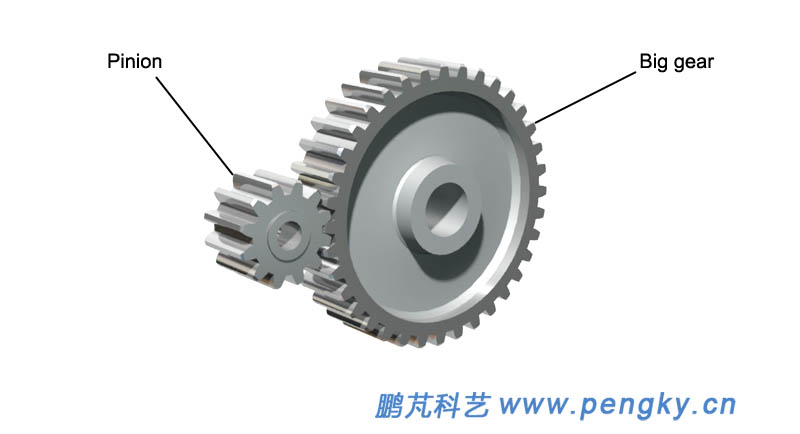 |
| Figure 1 - External gearing spur gear |
| The gear is fixedly installed on the rotating shaft, and the rolling bearing is installed at both ends of the shaft, as shown in figure 2. |
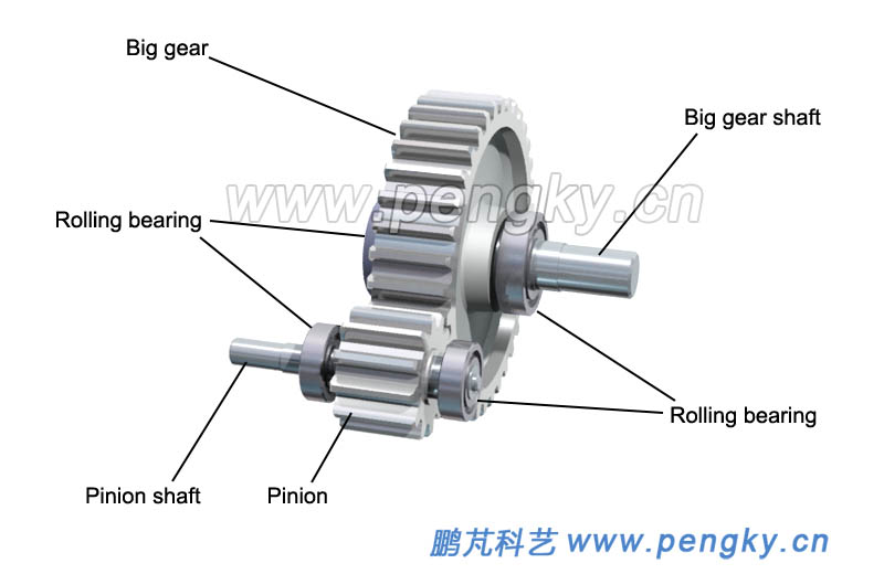 |
| Figure 2 - Gears and shafts |
| Install the gear in the pedestal (lower box), and install the main bearings in the corresponding bearing pedestal, as shown in figure 3. |
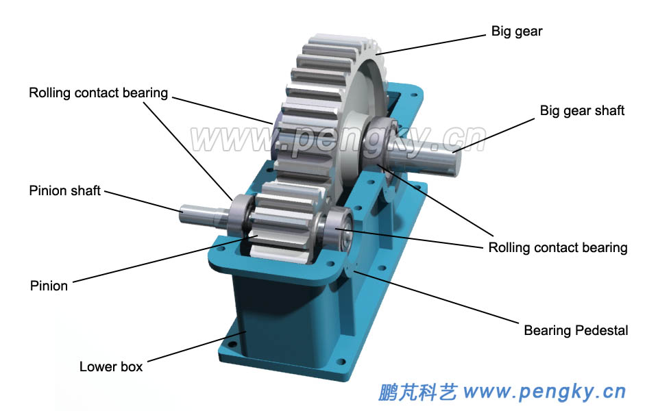 |
| Figure 3 - Primary cylindrical speed reducing gear box (1) |
| This is a primary gear drive mechanism, which is covered with a cover (upper box), which is a gear box. The pinion shaft input and large gear shaft output is a single-stage cylindrical gear speed reducer with a transmission ratio of 3; the large gear shaft input and pinion shaft output is a single-stage cylindrical speed-increasing gear with a gear ratio of 1/3. The maximum ratio of transmission of a single-stage cylindrical gear is 10, which is generally about 4. |
 |
| Figure 4 - Primary cylindrical speed reducing gear box (2) |
| Underside is the running animation of the gearbox |
| Primary cylindrical speed reducing gear box animation |
 |
Since gear transmission is used for deceleration in most applications, the gear transmission mechanism is generally referred to as a gear reducer, but it is used for speed increase in the main drive of the wind turbine. Cylindrical gears also have helical gears and herringbone gears. Figure 5 is a herringbone gear on the left and a helical gear on the right (picture from the network). |
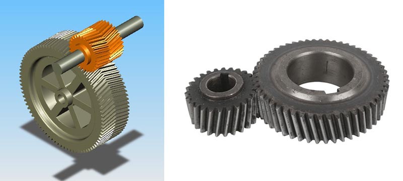 |
| Figure 5 - Herringbone gear and helical gear |
| Gearbox basic schematic symbol |
| Figure 6 is a basic schematic symbol of a cylindrical gears drive mechanism. |
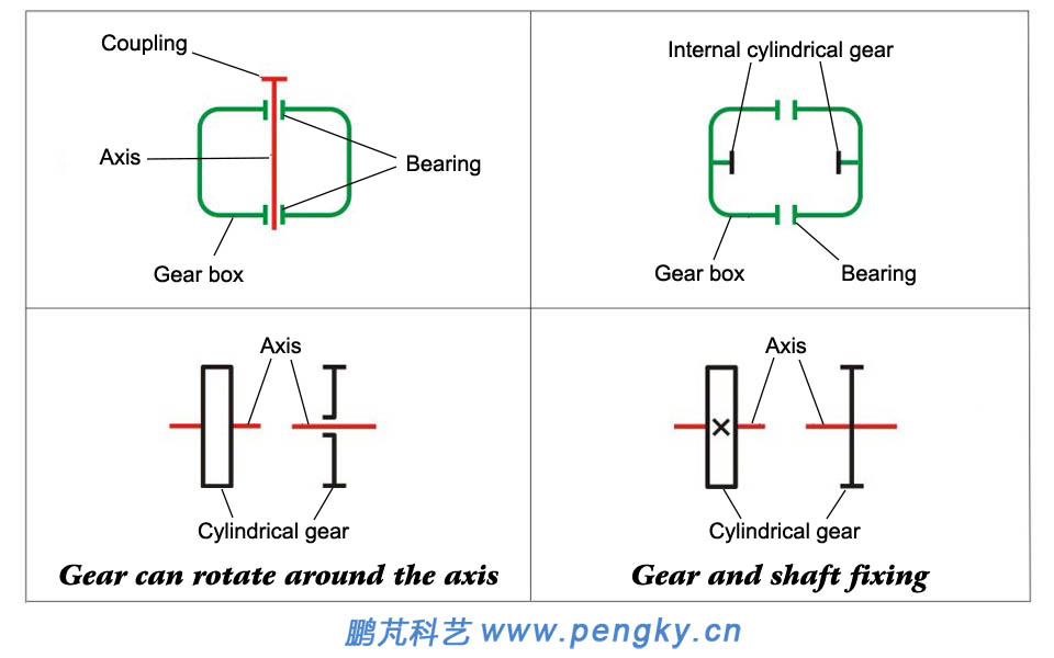 |
| Figure 6--Basic schematic symbol of cylindrical gears drive mechanism. |
| The primary cylinder speed reducing gear box shown in figure 4 can be represented by the simplified diagram shown in figure 7. |
 |
| Figure 7--Simplified diagram of the primary cylindrical speed reducing gear box |
| The main form of the cylindrical gears wind turbine speed-increasing gearbox |
| The transmission ratio of single-stage cylindrical gears geared speed ratio is very limited. In order to obtain a high speed ratio, multi-stage gears geared are required. The driven system composed of such multi-stage inter engaging gears is called a gear train. The following describes the forms of several multi-stage cylindrical gear speed increaser commonly used in wind turbines. In the introduction, the transmission ratio is calculated according to the decelerator. |
| Two-stage cylindrical gear drive |
 |
| The structure is simple, but the position of the gear relative to the bearing is asymmetrical, so the shaft is required to have a large rigidity. Generally used in applications where the load is relatively stable. The high speed stage is generally made of helical teeth, and the low speed grade can be made into straight tooth. The recommended transmission ratio is 8~40, and the maximum is 60. |
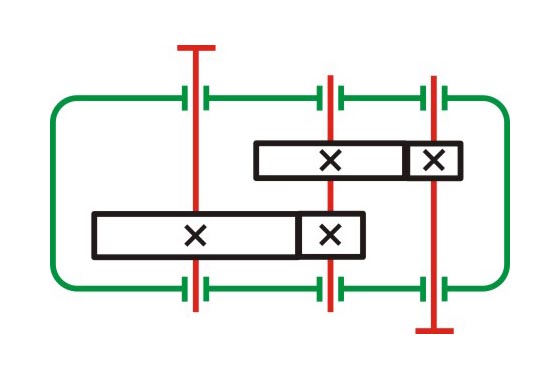
| Two-stage cylindrical gear transmission (distributary type) |
 |
| The structure is complicated, but since the gears are arranged symmetrically with respect to the bearing, compared with the unfolding type, the load is evenly distributed along the face width, and the bearing is evenly loaded. And is suitable for variable load applications. High-speed grades generally use helical gears, and low-speed grades can use straight or herringbone tooth. The recommended transmission ratio is 8~40, and the maximum is 60. |
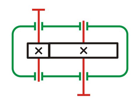
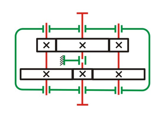
Two-stage cylindrical gear transmission (coaxial type) |
 |
| The transverse dimension size of the speed increaser is small, the depth of the two pairs of gears immersed in the oil is about the same, but the axial size and weight are large, and the input and output stages of the cylindrical gear drive are coaxial. The recommended transmission ratio is 8~40, and the maximum is 60. |
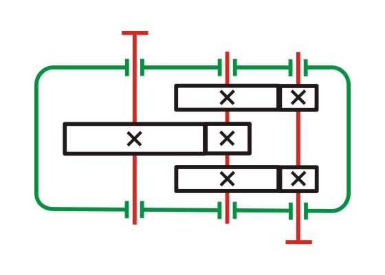
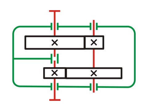
| Two-stage cylindrical gear transmission (coaxial split type) |
 |
Each pair of meshing gears transmits only half of the total load. The input and output shafts are only subjected to torque. The intermediate shaft is only half of the total load, so the neck journal size can be reduced compared to other speed of reducers that deliver the same power. The recommended transmission ratio is 8~40, and the maximum is 60. The above are the four commonly used structures. For large size wind turbines, the speed is slower and the speed increasing ratio is greater than 100. Generally, a 3-stage cylindrical gear increaser is used, in which each stage has an independent speed increasing ratio of 3 to 5. In practical applications, the combination of planetary gears and cylindrical gears is often used. |
| Back to Previous Page |
